Description
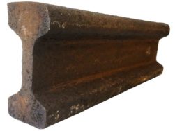
Two rail sections comprising a standard flat bottomed rail and a ‘Barlow’ type rail which was used on the Forth Bridge.
The rail used on the Forth Bridge is not a standard flat bottomed rail. The rail adopted for use on the Forth Bridge is known as a “Barlow” rail which has a saddleback section and is spiked directly onto the sleeper. Westhonen’s account reads:
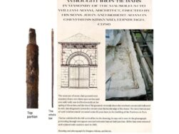
“The four rail-troughs in which the double line is laid are 18 in. in depth by 16 in. in width. (Fig. 155.[see image 2]) They are asphalted in the bottom to the level of the heel in the angle-bars, in order to make a water-tight bottom. Upon this bottom are laid transversely, about every 2 ft. 8 in. apart, blocks of teak about 5 in. square. Between these blocks the spaces are filled in with blocks of creosoted pine, all set about ⅛ in. to ¼ in. apart, and the whole is then filled up to level with a mixture of pitch and tar and black oil, which quickly sets hard.
“Stiffening plates of steel, about 6 in. wide and ¾ in. thick are riveted in about every 14 ft., and project about 2 in. above the teak blocks. All blocks are cut with an inward slope towards the centre of each line of about 1/2 in. to the foot.
“The whole mass of blocks and filling, which completely seals the lower portion of the trough, are now dressed for the reception of the longitudinal sleepers, which are about 12 in. by 5 ½ in., and also of teakwood. They are cut in lengths which are multiples of the 2 ft. 8 in. distance of the transverse blocks, and are notched where the plate-stiffeners occur. Play to the extent of 3/16 in. to ¼ in. is left between sleepers lengthwise.
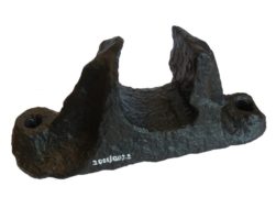
“Through the sleepers holes are bored every 2 ft. or 3 ft., and ¾ in. pins driven down into the blocks. The sleepers are kept in position transversely by wedge-shaped blocks of teakwood. The upper faces of the long sleepers are dressed to receive the rails of “bridge” section, the heaviest yet rolled weighing 120 lb. to the lineal yard. A section of the rail is shown in Fig. 156 [see image 3]. The rails are joined by a horizontal fish-plate underlying the flanges, and sunk into the sleepers with a projection entering into the hollow of the rail. The rails are screwed down by ¾-in, wood screws with hexagon heads. The total weight of rails, fish-plates, bolts, expansion joints, etc., for the double line of rails across the bridge and viaducts, is over 600 tons.
“The rail-troughs are drained of water through NA holes drilled into the sides every few feet at the a level of the top of the transverse blocking. In the floor of buckle-plates between the four troughs holes are placed to let the water through, these spaces being made up with asphalt mixture in such manner as to lead all the water to the outlets.
“The footpaths on each side of the double line are made up like ordinary pavements, on the system followed by the Seyssel Asphalt Company, the slope being such as to lead all water to the outer sides.”
WESTHOFEN, W. The Forth Bridge. Engineering, London, 1890.